Rogowski coil RS485
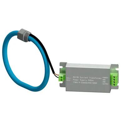
RS series Rogowski coil MODBUS RTU RS485 output can communicate with PLC,configuration software, configuration screen,etc.,solve the tedious work of the second design that the ordinary Rogowski coil can not be connected with the equipment.
This series of products are easy to operate,easy to install,and can be used for real-time monitoring,the Rogowski coil has a good isolation,this can be fully guaranteed and primary current isolation,to ensure safety.The series uses MODBUS RTU standard protocol format design.
Applications: · PLC,configuration software,Real-time monitoring system
- 必须有专门的软件、接口转换工具才能进行现场通讯。
There must be a special software, the interface conversion tool for field communication
- 举例说明(Example):
·1000A初级电流(1000A primary current)
输入(Input) : TX:01 03 00 00 00 02 (CRC校验码)
输出(OUTPUT) : RX:01 03 04 44 79 F5 E0 (CRC校验码)
转换(Converter) : [HEX] 44 79 F5 E0 -> [Float] 999.841797 (unit:A)
执行标准 Standards
·MODBUS RTU 协议标准
MODBUS RTU protocol standard
附注说明 Note
- 波特率选择,拨码开关共四挡位,1-4可选;默认波特率为9600,无奇偶校验位;需要打开铝壳上盖才能调节。
Baud rate selection, dial switch four block, 1-15 optional; default baud rate of 9600, no parity bit.Need to open the upper cover of aluminum shell to adjust.
(1)四个拨码全都拨到“ON”位置时,为“开”;
When all four dials are placed in the “ON” position, “ON” (2)四个拨码全都拨到“OFF”位置时,为“关”;
When all four dials are placed in the “OFF” position, “OFF”;
(3)最左边1为二进制最低位。
The left most 1 is binary (4) 地址表 Address list:
- 设备地址选择,拨码开关共四挡位,1-15可选;默认设备地址为01;需要打开铝壳上盖才能调节。
Device address selection, dial switch four block, 1-15 optional; default device address is 1;Need to open the upper cover of aluminum shell to adjust.
(1)四个拨码全都拨到“ON”位置时,为“开”;
When all four dials are placed in the “ON” position, “ON” (2)四个拨码全都拨到“OFF”位置时,为“关”;
When all four dials are placed in the “OFF” position, “OFF”;
(3)最左边1为二进制最低位。
The left most 1 is binary
- 读取输入寄存器(功能码 = 03)Read input register (function code = 03)。
·主机请求报文 Host request message
| 名称 Name | 长度 Length | 说明 Instruction |
|---|---|---|
| 设备地址 Device address | 1 byte | - |
| 功能码 Function code | 1 byte | 0x03 |
| 开始地址 Start address | 2 byte | 0x00 - 0xFFFF |
| 输入寄存器数量 Input-Register number | 2 byte | 1 - 125 (0x7D) |
| 校验码 CRC16-check | 2 byte | - |
·从设备应答报文Slave response message
| 名称 Name | 长度 Length | 说明 Instruction |
|---|---|---|
| 设备地址 Device address | 1 byte | - |
| 功能码 Function code | 1 byte | 0x03 |
| 输入寄存器数量对应字节数 Input-Register number | 1 byte | 2 * N |
| 输入寄存器数值1 Input-Register number | 2 byte | - |
| 输入寄存器数值2 Input-Register number | 2 byte | - |
| 输入寄存器数值n Input-Register number | 2 byte | n = N |
| 校验码 CRC16-check | 2 byte | - |
N=输入寄存器数量 Input-Register number
·从设备错误应答报文 Slave error response message
无错误应答报文,错误无输出或输出为00 00 00 00为错误应答报文
No error message, error no output or output is 00 00 00 00 error reply message